I've been experimenting with an Arduino UNO board for a couple of months now. It is pretty easy to use for simple digital and analog I/O. I can see how non-technical types like artists and designers might gravitate to it. It's quite fun to just write a few lines of code and presto! The LEDs are blinking! However, making LEDs blink is interesting for the first 20 minutes or so.
On the other hand, the art of push-button debouncing... that's another thing altogether. Seriously, I spent a few hours trying to figure out a debouncing algorithm that worked to my liking. I finally found some examples of software debouncers and adapted one of them.
Now, if I ever want a good debouncer, I will probably just implement it in hardware.
I've barely started into my main project, and frankly, I think I am already "outgrowing" my Arduino. I have found that parallel I/O is not a part of the standard library. I don't really understand why. I have found that there are ways to work around this, but really, how hard would it be to make it part of the standard library? (I know I can make my own lib. I will.)
Another thing that bothers me is the IDE. Its simplicity is great. But, it is missing certain features of good text editors that I miss. So, I think I'm going to have to figure out how to run the compiler & loader independent of the editor. My project will involve several hundreds of lines of code. So, this will be necessary before I get too far.
But before I start writing my app-specific software, I'd like to check out Arduino interrupt programming. I read that it supports internal timer event interrupts as well as external interrupts. I'd like to see them in action.
Wednesday, March 23, 2011
MSP430 Launchpad Arrived
While sharing some of my Arduino complaints with a friend of mine, he suggested I check out this cool new TI MSP430 Launchpad board. At under $5 (delivered!), I thought why not. I even talked a couple of other friends into buying one each. (Note: There's a max of 3 per order.)
If you check out the TI LaunchPad Wiki, I think you will agree it is worth picking up even if it sits on the shelf for a little while.
Oh and another thing... Hack-A-Day reported that someone is working on a header file that helps port Arduino sketches to TI Launchpad. So, I may start using this TI MCU sooner than later.
Wednesday, March 16, 2011
Featured on Hack-A-Day!
After some encouragement from a friend, I submitted my "Analog-to-"Digital Storage" Oscilloscope" hack to the Hack-A-Day website today and it made the cut. Thanks Hack-A-Day! (It is an honor.) I hope to have more postings featured there in the future.
Monday, March 14, 2011
Happy Pi Day!
I know. It is not a hack posting. But I can't just let this day go by without saying something. Pi has been an important part of my education and I think it is worth some some recognition for it's importance to the development of technology in modern society.
To celebrate, here is some music scored using Pi (video) and links to other Pi-related music and art work.
Happy Pi Day!
To celebrate, here is some music scored using Pi (video) and links to other Pi-related music and art work.
Happy Pi Day!
Saturday, March 5, 2011
Analog-to-"Digital Storage" Oscilloscope

In case you had not guessed already, this is a pretty simple hack that enables me to consistently take good quality digital photos of my analog scope display. By mounting a digital camera to the oscilloscope so that a low-light timed exposure can be taken, I do not have to use the camera flash and.

Materials:
- (1) analog oscilloscope (in my case Tektronics 2213A)
- (1) large plastic jar with a bottom large enough to span the scope display's width and height to enclose each of the bezel's edges.
- (1) digital camera (small, lightweight with timer)
- Velcro(TM) or adhesive hook strips and/or glue (hot glue gun)
- Sharp knife and/or Dremel tool
- Glue gun (optional)
- Tin snips / metal shears (optional)
Step 1: Go Nuts!
Empty a large plastic jar. Be sure to have a lid that is large enough to cut a hole for your camera lens and mount the digital camera to. You also need the bottom of the jar to span the outer part of the display bezel. For my case, the Kirkland Fancy Cashews jar worked great.
 |
| Testing Bottom of Plastic Jar for Size and Fit |
Step 2: Mark & Rough Cut Bottom of Jar
Measure the scope display and mark an outline on the bottom of the plastic jar. You can trim back the parts that will form the sides more than the top and bottom parts (relative to scope display). I recommend using a "paper-rub" to get the scope display dimensions perfect and be sure to mark for "under cutting" giving plenty of room to cut more as you fine-tune the fit.
 Paper rub of display outline.
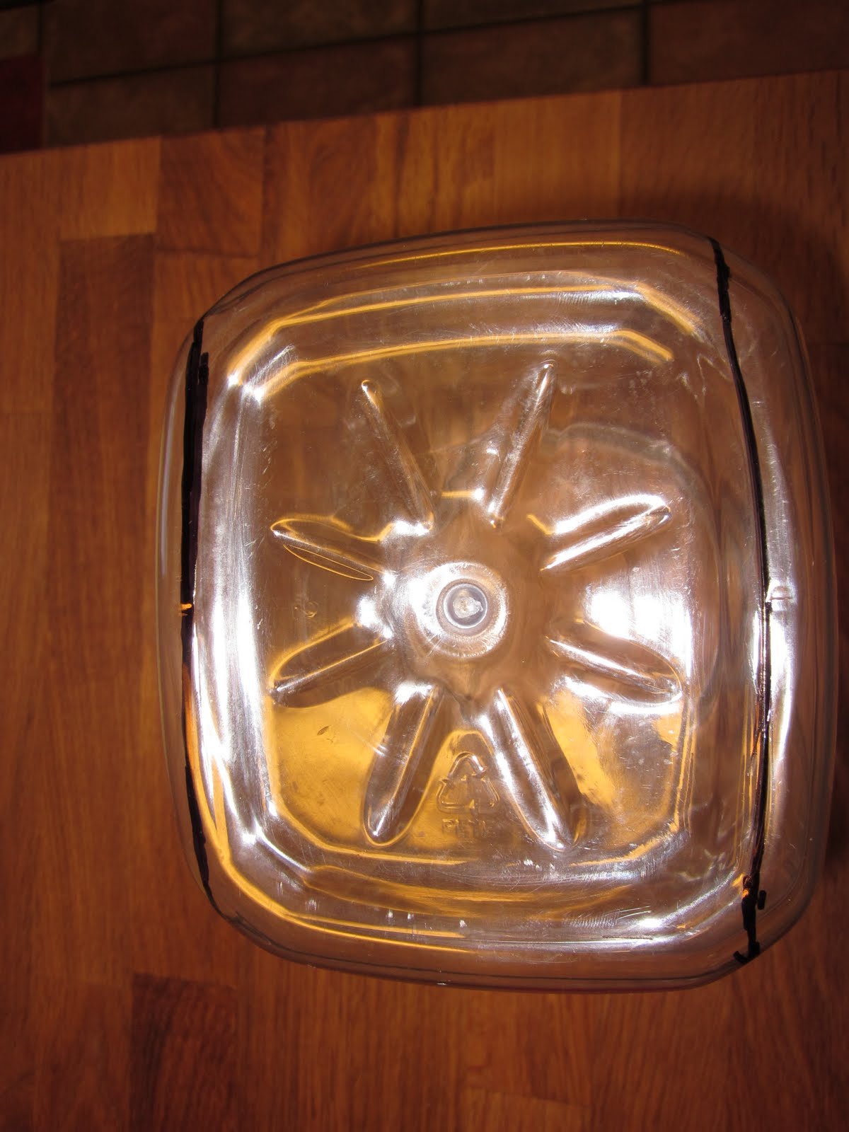 Marked for rough cut.
 Finished rough cut.
Since the jar is not perfectly square, start by cutting out the corner notches. This will make the fine cutting a little easier. To get the right fit takes some patience; Cut a little, measure and repeat until it fits "square" with the display. I recommend using tin snips or whatever else gives you a safe and controlled cut. At this point, you may also fold the top edge down to hook into the bezel groove. After the fold, more trimming may be required to set the other 3 edges (not-folded!) to be flush with the 90-degree-folded edge.
 Corner notch cut. (with folded top edge.)
 Corner notch cuts when connected to scope. (Note: Top fold fits into bezel groove.)
Step 4: Mark & Cut Jar Lid
Next, you need to determine the "12-o'clock" position of the lid and mark it. You can see the 12-o'clock position marked in the hole saw picture (below). This mark will be the 'up' position when the jar lid is attached to the jar while mounted on the scope.
Now, cut a hole in the lid that is at least the diameter of the camera lens. You may also consider cutting it large enough, or cut additional holes, to include the flash and any auto-focus assist light. I used a 1.5 inch hole saw on my drill press for a nice clean cut in the center of the lid.
 Clean cut with hole saw and drill press.
Step 5: Attach Mounting Hardware
To keep things simple, I used adhesive "hooks" product from 3M to attach the camera to the lid. The position of the adhesive will depend on where the "up" marking is and the camera. Below, are some pictures of the mounting hardware and assembly.


Rev 1.0: Finished
Well. That was it. But, I soon found several shortcomings:
- The hooks adhesive did not support the torque of the camera weight very well.
- I could not rotate the lid to adjust for the effect of the torque.
- The adhesive did not stick very well to the plastic lid.
- There is a lot of glare reflected from the display unless I turn off all lights behind the camera.


Rev 1.1: Summary
So I made some minor changes to improve the performance of this camera mount:
- Fashioned some "L" brackets from some scrap metal I had in my shop.
- Created a cardboard platform to set the camera on.
- Set the camera platform so that it was plumb at 1-o'clock instead of 12-o'clock. This makes it possible to rotate the camera within 10 to 15 degrees of plumb vertical.
- Painted the inside of the lid side of the jar matte black to reduce glare from outside light sources
- These improvements are illustrated in the following pics.


Final Thoughts
Well, I basically got what I wanted; a way to take crisp clear pictures of my oscilloscope display. I still need to figure out how to illuminate the grid from within the jar. I may add some LEDs. But, I may have to deal with glare again...
This project got me thinking about some other hack ideas:
- I've found that single-shot capture is may be necessary for some IR hacks. (Depends on the IR remote used. So, it got me thinking about if/how I could trigger the digital camera "shutter" to synchronize off of the scope trigger. Ideally, I could implement a "single-shot" capture like a real DSO.
- An even more ambitious idea: Hack the internal display control voltages and use an ADC to capture the waveform.
- Add support to make the scope a multi-channel (>2 chan) digital logic analyzer/display. (Hack-a-Day recently had a post on this. (See: http://hackaday.com/2010/02/11/use-an-analog-oscilloscope-to-display-digital-logic/)).
Tuesday, March 1, 2011
My First O'scope!
A couple of weeks ago, I bought my first oscilloscope. It is a used Tek 2213A (2-chan, 60MHz, analog). (I got a great deal... less than $100 with 2 passive probes.) I've already used it to decode some IR flasher codes and based on that experience, I've already cooked up a hack to make it a "digital storage" scope. I'll post that hack later this week.
Overall, I am happy with the new 'scope. But, I have definitely gotten a little dumbed-down using digital scopes over the years. Seriously, I spent an hour thinking I had bought a dud, trying to figure out where my traces were. I went so far as to open the case to see if any components were visibly fried. Then, I read "step 1" of the service manual. It goes something like "...turn the display intensity knob to max position..." and just like that I was in business. What can I say? I am a little rusty.
Overall, I am happy with the new 'scope. But, I have definitely gotten a little dumbed-down using digital scopes over the years. Seriously, I spent an hour thinking I had bought a dud, trying to figure out where my traces were. I went so far as to open the case to see if any components were visibly fried. Then, I read "step 1" of the service manual. It goes something like "...turn the display intensity knob to max position..." and just like that I was in business. What can I say? I am a little rusty.
Subscribe to:
Posts (Atom)